
Please leave an entry in the guestbook, if you want to be informed about news and changes.
2002-11-10: The problem is solved: Change R18 from 3k3 to 3k9 and it will work! I changed the schematic, the BMP-File is now zipped and in 300dpi-quality.
The votes helped me to decide to use SMD-parts whereever possible. I'm working on the PCB now.
2002-11-06: The PTT-part of the board is not working in a cold environment - I'm looking for a solution!
2002-11-04: Our first pair of UserRX is running in a testlink over
650m, with very poor antennas and good results!
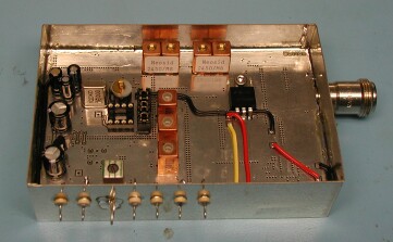
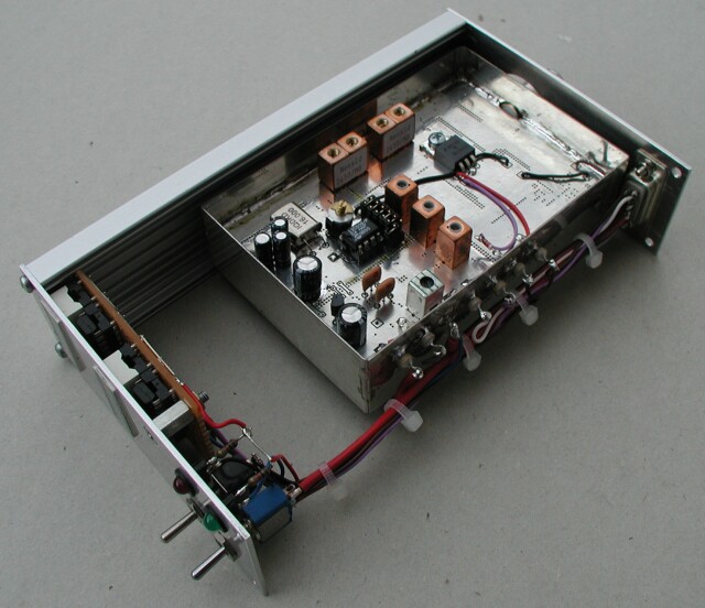
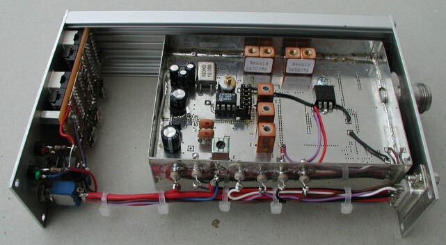
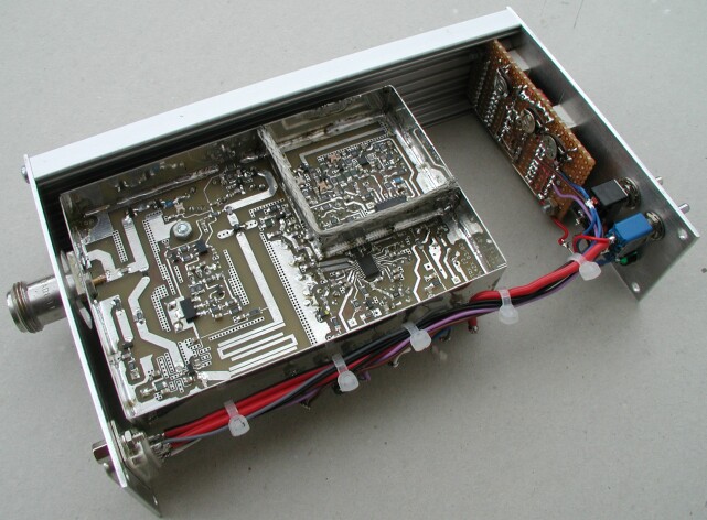
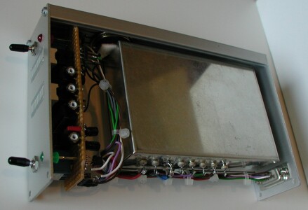
Martin, DL4ZX, developed a really nice Packet-Radio-TRX for 13cm. The housing is 70x110mm small, it fits into a standard ISEL-TNC-housing. You can see some pictures of a UserTRX I built for a link DB0TTM-DB0TTH. The front-board here is a pretty early version of the one described on this page. Click to enlarge the pictures.
The inner housing is fixed to the outer one with two 8mm long bolts for 3mm screws. The bolts are soldered to the inner housing and screwed to the outer with countersunk screws.
Here you can find a zipped drilling plan for the inner housing - may save some time. Or the raw .bmp-plan.
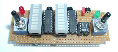
To give this box something like an 'user-interface', I worked with Martin on a small PCB, that offers these features:
This is a picture of the prototype:
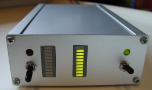
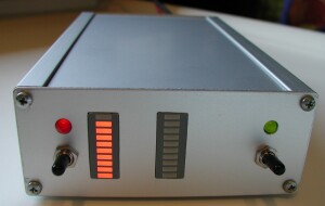
Here integrated in a TRX:
No changes on the UserTRX 13 are needed. The circuit is tested, the final layout of the PCB-board is still to finish.
With some changes you can use the board for other TRXs. Especially for Martins 70cm-wide-band-TRX a description of the (small) changes in partvalues will follow. For PWR-measurement you have to add an easy coupler in the PA of the TRX.
It is a non-commercial project, but to help HAMs to build up the board easily, I will offer PCBs for the cost of production. Please contact me via E-mail.
Here you find the schematic as Postscript, bmp (zipped) und Eagle4.0.
And a wiring scheme how to connect the Front-board to the UTRX and the outer world (as Postscript, bmp (zipped) and Eagle4.0). The pinout for the SubD-connector is similar to the Baycom FlexEPP-Modems. There is no separat DC-plug used - no space on the backside of the housing.
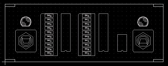
The layout is under construction, the files will give the actual state to you. But the following picture shows the position of visible elements and the outline of the board. Vote if I should use SMD-parts!
If you would like to use the circuit for some other TRXs, you have some documented possibilities to change values or omit parts.
The S-meter is realized with the LM3914 (locally stored data sheet here). There are two potentiometers to adjust offset (P2) and scale (P1). The range for the offset is calculated from 0.4V to 1.25V, the value can be measured on pin 4 of the LM3914. The range of the change from no signal to maximum signal is calculated from 0.4V to 1.25V, too. The voltage at pin 6 is the upper limit. By changing P1, P2, R1 and R2, you can vary these values - but with this circuit, the maximum scale is limited to 1.25V. Please look at the data sheet.
With SJ1 shortened you put the LM3914 in the barmode. I like it more, but it costs some 10mA of current. If you leave it open, the signal strength will be displayed as a dot - and the activation of the AF-amplifier will not work correctly. In this case or if you don't need the squelch-function, T3x and R3x are not needed. If you use the squelch function you can change the level by selecting the first or second LED to control the switch. Never shorten SJ3 and SJ4 at the same time!
The PWR-meter is a bit easier, there is no offset. The scale can be adjusted by P3 between 0.7V and 1.5V.
Leaving SJ2 open, the LM3914 is in dotmode.
This part of the circuit is somewhat special for the UTRX13. The TRX has a PLL-error signal FOLD, that has three states:
T1 switches LED1 on, if the PLLs are locked, T2 and T3 prevent the PLL of the TRX from being activated, if they are not. The values of the resistors are a bit critical.
If you don't need this feature, shorten SJ5, D1, D2 and emitter and collector of T1. D1-2, T1-3 and R16-18 are not needed. Or just put FOLD to 12V...
T5 pulls the modulation to GND, if there is no PTT. If C4 and C5 are needed, is a question of the DC-level of your modem and TRX. There should be no problem using them, but if there is no DC on your modulation, vou can shorten them.